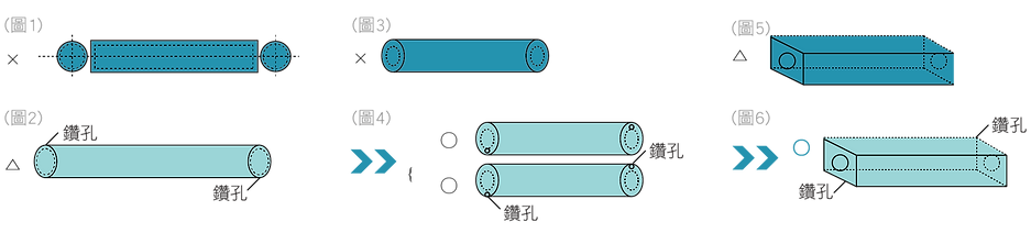
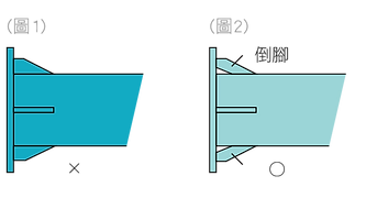
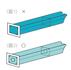
As shown in Figure 1, the sealed state cannot be immersed due to buoyancy, so it is necessary to open air holes at both ends. The location of the holes is as shown in Figure 2. Please make holes at the top of the diagonal line.
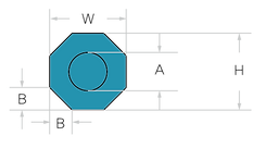
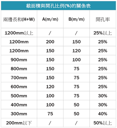
The diameter of the opening varies depending on the size of the tube, please refer to the table above.
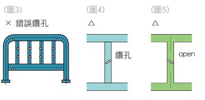
As shown in Figures 3 and 5, when the holes are located in the center, there will be air retention on the one hand, and scars or lumps on the corners.
Therefore, holes must be made at the locations shown in Figures 4 and 6.
02
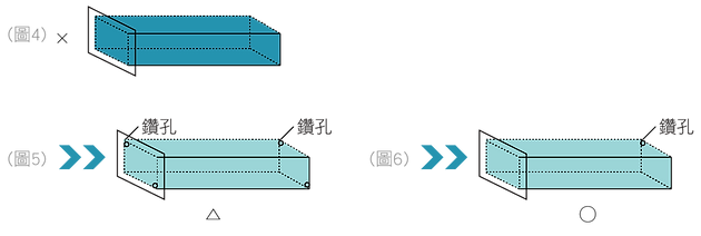
Sealing structure including flange
As shown in Figure 1 and Figure 4, the parts are closed with flanges at both ends. In this type of structure, air cannot be discharged and zinc liquid cannot enter.
Figure 2 and Figure 5 show the components after being drilled so that both air and zinc liquid can circulate.
As shown in Figure 3 and Figure 6, the closed end of the flange is hollowed out, and a vent hole is drilled at the other end. This treatment is most conducive to the galvanizing operation.
03
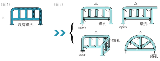
Sealing structure processed products (railings)
Figure 1 shows that it is completely closed so that air cannot be discharged and zinc liquid cannot flow in, which will lead to poor galvanizing. Figure 2 shows the top and bottom of each closed tube. It is necessary to drill diagonal holes at both ends and hollow out the base of the tube.
04
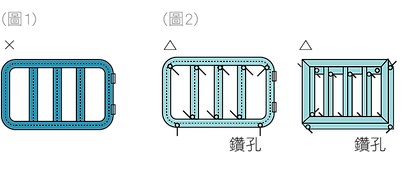
Sealed structure processed products
As shown in Figure 1, everything is completely sealed, air cannot be discharged, and zinc liquid cannot invade.
Figure 2 In addition to drilling the upper and lower pipes diagonally, the pipes on the four sides must also be drilled on the lower edges of the four corners.
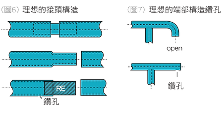
The drilling position shown in Figure 3 is completely correct and must be at the end points of both ends, as shown in Figure 4.
Figure 5 is the best way to deal with it, through the connection part of the pipe.
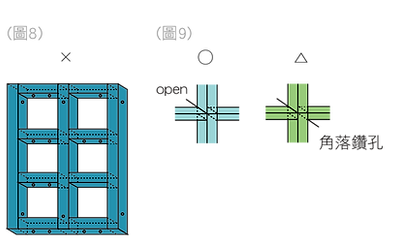
Figure 8 is the structural diagram of a square tube. There are no air outlets and zinc leak holes at the ends, which will cause the retention of air and zinc liquid during galvanizing operations.
Figure 9: Drill holes in the corners, or hollow out the joints of square pipes to facilitate the inflow and outflow of zinc liquid.
05
When there is a cannula inside
The pipe fitting in Figure 1 contains a dead space with an inner tube, which will generate buoyancy and prevent the zinc liquid from being completely immersed.
Figure 2 shows the ideal processing method.
06
Where to strengthen the terminal version
The edge of the reinforcing material at the end of Figure 1 may have trapped air and molten zinc, so the chamfer must be reserved as shown in Figure 2 before welding.
07
Places containing reinforcing materials
If a joint with a gap is immersed in a high-temperature galvanizing bath, the air and moisture contained in it will expand rapidly, up to dozens of times. Such high pressure will cause an explosion from the poorly welded area, which is very dangerous.
08
When there is a reinforcing plate inside
When there are reinforcing plates inside, adequate openings are necessary. If the proportion of openings is too small, it will easily lead to ash burning.